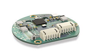
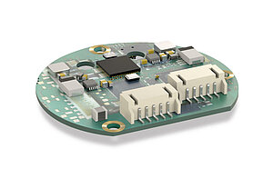
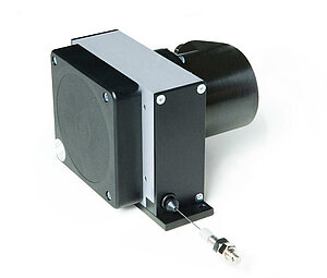
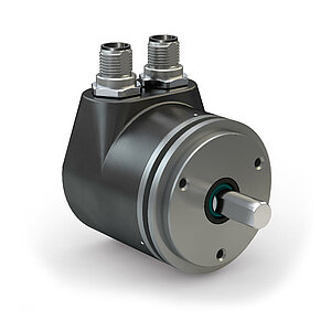
Absolute encoder WV58MR-Testprodukt
absolute redundant safety encoders
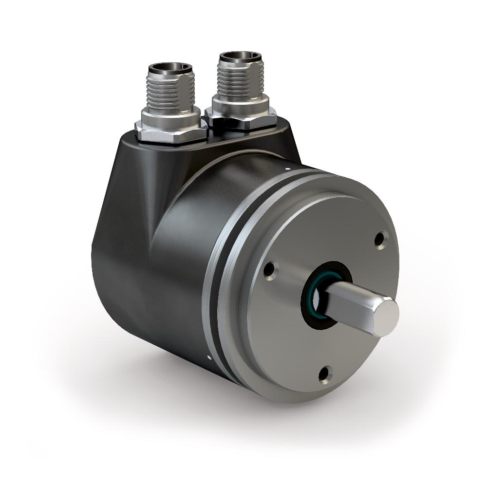


- absolute redundant safety encoders
- CANopen Safety or CANopen redundant interface
- Can be used in applications up to performance level PLd
- Salt spray tested housing available
- High EMC compatibility
- available with special slewing ring functionality
- With PURE.MOBILE technology
Note
Voltage drop should be envisaged with increasing cable length. This should be taken into account for the electrical design.
Technical drawing

Technical data
Calculation of the measurement angle
Circumferential speed
Rotational speed, Moment of inertia, Weight
|
"Pole number " |
70 |
86 |
102 |
128 |
158 |
224 |
396 |
|
Rotational speed |
10500 min |
8800 min |
7400 min |
5800 min |
4700 min |
3300 min |
1900 min |
|
Moment of inertia |
≥85 gcm |
≥178 gcm |
≥326 gcm |
≥752 gcm |
≥1525 gcm |
≥5056 gcm |
≥38040 gcm |
|
Weight |
25 g |
33 g |
41 g |
58 g |
74 g |
116 g |
266 g |
Dimensions
|
code size |
Measurement A [mm] |
Measurement B [mm] |
Measurement øC [mm] |
Measurement angle a [°] |
Measurement length l [mm] |
|
7 Bit |
11.1 |
35 |
≥384 |
<190 * |
≤640 |
|
8 Bit |
8.6 |
40 |
≥501 |
<290 * |
≤1280 |
|
9 Bit |
6.1 |
45 |
≥634 |
≤2560 |
|
|
10 Bit |
3.6 |
50 |
≥782 |
≤5120 |
|
|
11 Bit |
1.1 |
55 |
≥946 |
≤10240 |
Calculation of the "required tape length b" see order
|
Hub |
øD |
ødv |
ødx |
ød1 |
ød2 |
ød3 |
a |
b |
c |
e |
f |
h |
Suitable for |
|
|
HG5 |
plastic |
63 |
6 … 12 |
13 |
21 |
58 |
49 |
28.9 |
14.3 |
19.2 |
17.2 |
14.3 |
S50/1 |
|
|
metal |
63 |
5.8 |
6 … 14 |
18 |
26 |
58 |
52 |
28.9 |
13.3 |
22.2 |
14.3 |
17.3 |
S50/1 |
|
|
HG10 |
plastic |
98 |
6 … 16 |
16 |
30 |
93 |
56 |
31.5 |
18.7 |
22.8 |
20.7 |
18.7 |
S80/1; SZ80/1 |
|
|
metal |
98 |
5.8 |
6 … 16 |
25.5 |
35 |
93 |
59 |
31.5 |
18.2 |
25.8 |
18 |
21.7 |
S80/1; SZ80/1 |
|
|
2 |
3 |
2 |
2 |
2 |
2 |
2 |
2 |
2 |
2 |
2 |
2 |
2 |
2 |
4 |
|
Hub |
øD |
ødv |
ødx |
ød1 |
ød2 |
ød3 |
a |
b |
c |
e |
f |
h |
Suitable for |
|
plastic |
63 |
6 … 12 |
13 |
21 |
58 |
49 |
28.9 |
14.3 |
19.2 |
17.2 |
14.3 |
S50/1 |
|
|
metal |
63 |
5.8 |
6 … 14 |
18 |
26 |
58 |
52 |
28.9 |
13.3 |
22.2 |
14.3 |
17.3 |
S50/1 |
|
3 |
2 |
2 |
3 |
2 |
2 |
2 |
2 |
2 |
2 |
2 |
2 |
2 |
3 |
special processing
|
Handwheel type |
HG10 |
|||
|
Bore dH7 |
6 … 8 |
9, 10 |
11, 12 |
13 …16 |
|
Groove width with keyway JS9 |
3 |
4 |
5 |
|
|
Pin hole |
3.8/10 |
3.8/10 |
3.8/10 |
4.8/10 |
|
Hub thread without keyway JS9 |
M4/10 |
M4/10 |
M4/10 |
M6/10 |
|
Hub thread with keyway JS9 |
M3/10 |
M3/10 |
M4/10 |
|
|
3 |
2 |
2 |
2 |
2 |
Highlights in blue are order features.
|
Handwheel type |
HG5 |
|||
|
Bore dH7 |
8 |
10 |
12 |
14* |
|
Groove width with keyway JS9 |
3 |
4 |
5 |
|
|
Pin hole |
3.8/10 |
3.8/10 |
3.8/10 |
4.8/10* |
|
Hub thread without keyway JS9 |
M4/10 |
M4/10 |
M4/10* |
M6/10* |
|
Hub thread with keyway JS9 |
M3/10 |
M3/10 |
M3/10 |
|
|
3 |
2 |
2 |
2 |
2 |
Highlights in blue are order features.
Travel/circumferential speed
|
Travel/circumferential speed Vmax [m/s] |
|||||||||||
|
Resolution/ Scaling factor |
0.001/1250 |
4.00 |
3.20 |
1.60 |
0.80 |
0.32 |
0.20 |
0.10 |
0.05 |
0.03 |
0.01 |
|
0.005/250 |
20.00 |
16.00 |
8.00 |
4.00 |
1.60 |
1.00 |
0.50 |
0.25 |
0.13 |
0.06 |
|
|
0.01/125 |
25.00 |
25.00 |
16.00 |
8.00 |
3.20 |
2.00 |
1.00 |
0.50 |
0.25 |
0.12 |
|
|
0.025/50 |
25.00 |
25.00 |
25.00 |
20.00 |
8.00 |
5.00 |
2.50 |
1.25 |
0.63 |
0.30 |
|
|
0.05/25 |
25.00 |
25.00 |
25.00 |
25.00 |
16.00 |
10.00 |
5.00 |
2.50 |
1.25 |
0.61 |
|
|
0.1/12.5 |
25.00 |
25.00 |
25.00 |
25.00 |
25.00 |
20.00 |
10.00 |
5.00 |
2.50 |
1.21 |
|
|
Pulse interval [μs] |
0.20 |
0.25 |
0.50 |
1.00 |
2.50 |
4.00 |
8.00 |
16.00 |
32.00 |
66.00 |
|
|
Counting frequency [kHz] |
1250.00 |
1000.00 |
500.00 |
250.00 |
100.00 |
62.50 |
31.25 |
15.63 |
7.81 |
3.79 |
|
|
10 |
4 |
3 |
3 |
3 |
3 |
3 |
3 |
3 |
3 |
3 |
3 |
max. speed
|
Display (after 1st revolution) |
max. speed [rpm] |
|
0010 |
500 (1500) |
|
0015 |
500 (1000) |
|
0020 |
500 (750) |
|
0025 |
500 (600) |
|
0030 |
500 |
|
0040 |
375 |
|
0050 |
300 |
|
0060 |
275 |
|
0080 |
180 |
|
0100 |
150 |
Note
Speeds >500 rpm must only be run for short periods.
|
RH01 |
RH02 |
RH03 |
RH04 |
RH05 |
RH07 |
RH08 |
RH09 |
|
|
compatible with display |
DA05/1 DA08 DA09S DE10*** |
DA10* DA10R/1* DE10**** DE10P |
DA10** DA10R/1** |
DA04 DE04 |
KP09P |
DA02 DK05 |
DK01 DK02 |
AP05 AP10*** AP20*** GS04 |
|
ødH7 steel, burnished |
6, 6.35, 8, 10, 12, 12.7, 14, 15, 15.875, 16, 17, 18 |
10, 12, 12.7, 14, 15, 16, 18, 19.05, 20, 22, 24, 25, 25.4, 26, 28 |
18, 20, 22 |
4, 5, 6, 6.35, 8, 9.525, 10, 12 |
12, 14, 15, 16, 20 |
6, 6.35, 7, 8 |
5, 6, 6.35, 8, 9, 9.525, 10, 12 |
|
|
ødH7 stainless steel |
VA8, VA9.525, VA10, VA12, VA12.7, VA14, VA15, VA15.875, VA16, VA19.05 |
VA12.7, VA20, VA24, VA25, VA25.4 |
VA6.35, VA8, VA9.525, VA10, VA12, VA12.7, VA13 |
VA8 |
VA8, VA9.525, VA10, VA12, VA12.7, VA14, VA15, VA15.875, VA16, VA18, VA19.05 |
Note: Highlights in orange are order features.
Subheading 1 Test
Signal pattern, Sin/Cos output
F: 1 VSS ±10 %
L: 180° ±40 %
M: 90° ±1.0° / ±3° (25 kHz)
X: 1 VSS
Signal image

|
E: |
1.65 V (reference voltage) |
|
F: |
2.5 V |
|
L: |
360° |
|
M1: |
90° |
|
M2: |
180° |
|
M3*: |
355° ±15° (ELP25) |
|
90° ±15° (ELP50) |
|
|
85° ±15° (ELP100) |
|
|
X: |
+UB |
Note: 360° = Pole length
Signal pattern, LD output circuit
Note
The logic status of signals A and B is not defined regarding the reference signal RD or R. It may deviate from the signal pattern.
Note
Reference or index signal with 4 increments (360°) signal length is only valid from the 5th counting step onwards. A corresponding delay should be taken into consideration after switching on the operating voltage.
pulses/revolution
|
"Pole number " |
460 |
540 |
720 |
1120 |
|
Period |
460 |
540 |
720 |
1120 |
|
"Pole number " |
50 |
64 |
100 |
230 |
|
|
Scaling factor of sensor |
20 |
1000 |
1280 |
2000 |
4600 |
|
16 |
800 |
1024 |
1600 |
3680 |
|
|
10 |
500 |
640 |
1000 |
2300 |
|
|
8 |
400 |
512 |
800 |
1840 |
|
|
5 |
250 |
320 |
500 |
1150 |
|
|
4 |
200 |
256 |
400 |
920 |
|
|
1 |
50 |
64 |
100 |
230 |
|
|
2 |
1 |
2 |
2 |
2 |
2 |
Subheading 1 Test
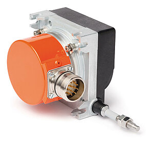
More information
Rotary encoders that can be combined with this wire-actuated encoder
- for analog outputs such as current or voltage: AV3650M, AV58M
- for incremental outputs: IV5800
- for absolute outputs: WV58MR, WV5800M, WV5850, WV3650M, WV36M/CAN
The technical specifications for these devices can be found in the respective data sheets. In addition, numerous encoder variants from different manufacturers can be used.
Rotary encoders that can be combined with this wire-actuated encoder
LEERZEILE(n)
Aufzählung
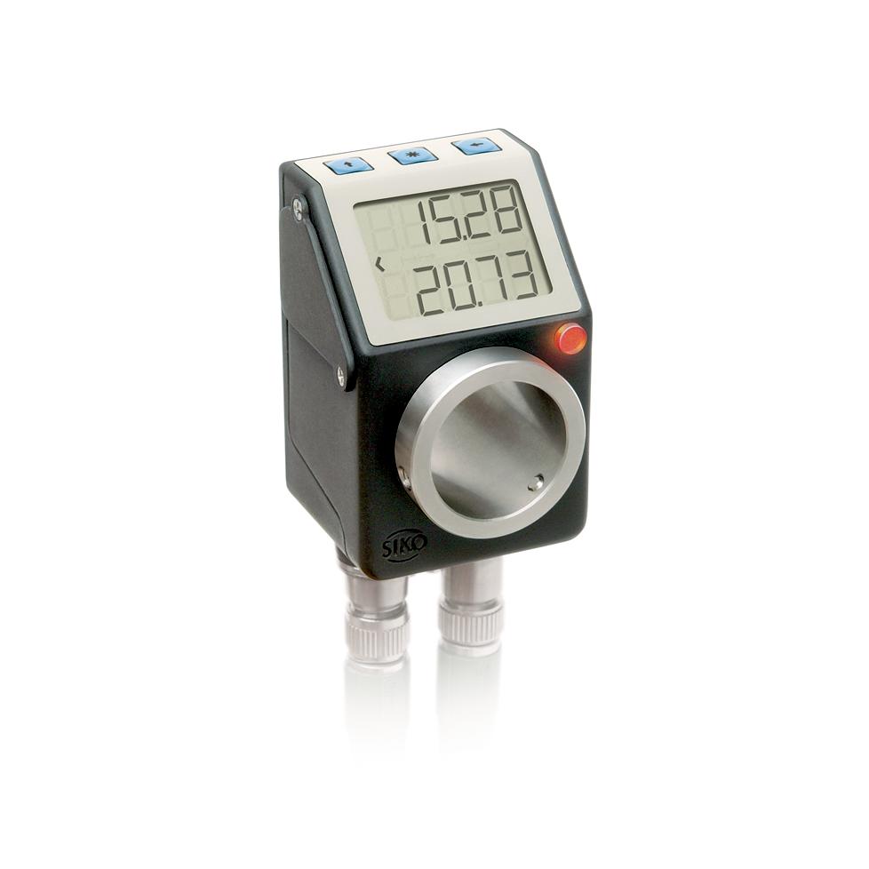
Option, PURE.MOBILE sensor module
Inclinometer
|
Feature |
Technical data |
Additional information |
|
Resolution |
0.01° |
|
|
Measuring range |
360° |
1 axis |
|
±180° |
1 axis |
|
|
Accuracy |
±0.1° at 20 °C |
|
|
±0.8° |
over the entire temperature and max. measuring range |
|
|
Zero point accuracy drift max. |
±0.02 °/K |
|
|
Zero point accuracy drift typical |
±0.008 °/K |
|
|
Cut-off frequency |
10 Hz |
|
|
36 |
42 |
88 |
System resolution MRAC501 with MSAC501
System resolution* absolute and incremental [bit]
|
Total bits/revolution |
||
|
Scaling MSAC501 magnetic sensor |
7 bit |
15 |
|
8 bit |
16 |
|
|
9 bit |
17 |
|
|
10 bit |
18 |
|
|
Number of poles of MRAC501 magnetic ring |
256 (8 bit) |
|
|
3 |
1 |
4 |
System resolution* absolute [steps/revolution]
|
Bits/revolution |
steps per revolution |
Resolution |
|
15 |
32768 |
0.011° (39.6") |
|
16 |
65536 |
0.0055° (19.8") |
|
17 |
131072 |
0.0027° (9.9") |
|
18 |
262144 |
0.0014° (4.9") |
System resolution incremental [steps/revolution]
|
Bits/revolution |
Steps per revolution** |
Resolution** |
|
15 |
131072 |
0.0027° (9.9") |
|
16 |
262144 |
0.0014° (4.9") |
|
17 |
524288 |
0.0007° (2.5") |
|
18 |
1048576 |
0.0003° (1.2") |
**After 4-fold evaluation of the incremental signals
Rotational speed of MRAC501 with MSAC501
incremental, code size 8 bits, 256 poles
|
Speed [rpm] |
||||||||||
|
Incremental scaling MSAC501 magnetic sensor |
7 bit |
1172 |
732 |
366 |
146 |
92 |
46 |
23 |
11.4 |
5.6 |
|
8 bit |
916 |
366 |
183 |
73 |
46 |
23 |
11.4 |
5.7 |
2.8 |
|
|
9 bit |
458 |
183 |
92 |
37 |
23 |
11.4 |
5.7 |
2.9 |
1.39 |
|
|
10 bit |
229 |
92 |
46 |
18.3 |
11.4 |
5.7 |
2.9 |
1.43 |
0.69 |
|
|
Pulse interval [µs] |
0.2 |
0.5 |
1 |
2.5 |
4 |
8 |
16 |
32 |
66 |
|
|
Counting frequency [kHz] |
1250 |
500 |
250 |
100 |
62.5 |
31.25 |
15.63 |
7.81 |
3.79 |
|
|
3 |
1 |
1 |
1 |
1 |
1 |
1 |
1 |
1 |
1 |
1 |
Absolute
|
code size |
Speed [rpm] |
|
8 bit |
234 |
pin assignment
E12, E12E, E12EE
|
Signal |
PIN |
|
CAN_GND |
1 |
|
+UB |
2 |
|
GND |
3 |
|
CAN_H |
4 |
|
CAN_L |
5 |
E1
|
Signal |
Cable color E1 |
|
CAN_GND |
white |
|
+UB |
brown |
|
GND |
green |
|
CAN_H |
yellow |
|
CAN_L |
gray |
pin assignment
Potentiometric outputs P01, P05, P10
|
Signal |
Terminal |
|
Po |
11 |
|
Pe |
13 |
|
S |
12 |
MMW transducer
|
Signal |
Terminal |
|
I+ |
12 |
|
I- |
11 |
|
nc |
13 |
Cam
|
Assignment |
Switch cam A Terminal |
Switching cam B terminal |
Switching cam C terminal |
|
|
3 |
4 |
7 |
|
2 |
5 |
8 |
|
|
1 |
6 |
9 |
Performance curve

Industry 4.0
|
Process data |
Smart Value |
Smart Function |
|
Actual position |
Temperature |
Overlaod, ambient temperature |
|
"Target position " |
current |
Torque, overload |
|
Speed |
Volatage load Voltage control |
Voltage drop, line break |
|
On/Off time |
Operating time |
|
|
Battery voltage |
Battery change planning |
Hint for mounting
|
Reference signal |
O, I |
R |
FR |
|
A, Sensor/tape reading distance |
≤2 mm |
≤1.5 mm |
0.4 … 1.0 mm |
|
B, Lateral offset |
±2 mm |
±0.5 mm |
±0.5 mm |
|
C, Alignment error |
±3° |
±3° |
±3° |
|
D, Longitudinal inclination |
±1° |
±1° |
±1° |
|
E, Lateral inclination |
±3° |
±3° |
±3° |
|
2 |
1 |
1 |
1 |
Hint for mounting
|
A, Sensor/tape reading distance |
≤0.4 mm |
|
B, Lateral offset |
±0.5 mm |
|
C, Alignment error |
±1° |
|
D, Longitudinal inclination |
±1° |
|
E, Lateral inclination |
±2° |
Data Matrix Code
Itemization
17 characters[Item number (5-digit)]
[Comma]
[Year/calender week YY/WW (5-digit)]
[Comma]
[Consecutive numbering (5-digit)]
Example:
Item number 88870, Production year 2017 / -week 21, Consecutive number 12345
88870,17/21,12345
Error correction according to ECC200


Order
Ordering information
The necessary tape length is calculated from:Measured distance + sensor length "S" + (2 x forerun or overrun "B", resp.).
|
S |
see the drawing of the sensor used |
|
B |
10 mm (forerun and overrun) |
|
1 |
7 |
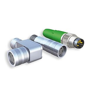
Overview of orders
|
Order key |
Photo |
Type |
PIN |
Designation |
ø Cable |
øD |
l |
b |
h |
a |
|
71364+71365 |
5 |
D-SUB |
9 |
pin+shell |
≤8.5 |
35 |
31 |
15.5 |
||
|
71366+71365 |
5 |
D-SUB |
9 |
socket+shell |
≤8.5 |
35 |
31 |
15.5 |
||
|
73947+73946 |
5 |
D-SUB |
15 |
socket+shell |
≤8.5 |
42 |
40 |
15.2 |
||
|
76141 |
1 |
M16 |
7 |
bushing |
4 … 6 |
18.5 |
61 |
|||
|
76572 |
1 |
M16 |
12 |
bushing |
6 … 8 |
18.5 |
62 |
|||
|
77087 |
1 |
M16 |
7 |
bushing |
6 … 8 |
18.5 |
62 |
|||
|
78088 |
4 |
M16 |
7 |
"angle socket " |
4 … 6 |
20 |
38 |
54 |
||
|
79665 |
4 |
M16 |
7 |
"angle socket " |
6 … 8 |
20 |
38 |
54 |
||
|
79666 |
4 |
M16 |
12 |
"angle socket " |
6 … 8 |
20 |
38 |
54 |
||
|
81351 |
1 |
M9 |
8 |
bushing |
3.5 … 5 |
14 |
38 |
|||
|
81363 |
4 |
M16 |
3 |
"angle socket " |
4 … 6 |
20 |
38 |
54 |
||
|
81487 |
1 |
M9 |
3 |
bushing |
3.5 … 5 |
14 |
38 |
|||
|
81935 |
1 |
M23 |
12 |
bushing |
≤8.5 |
26 |
51.1 |
|||
|
82182 |
1 |
M16 |
3 |
bushing |
4 … 6 |
18.5 |
61 |
|||
|
82247 |
4 |
M9 |
4 |
"angle socket " |
3.5 … 5 |
14 |
30 |
30.5 |
||
|
82366 |
4 |
M9 |
3 |
"angle socket " |
3.5 … 5 |
14 |
30 |
30.5 |
||
|
82804 |
7 |
M12 B-Cod. |
5 |
"angle socket " |
4 … 8 |
19 |
48 |
41 |
100° |
|
|
82805 |
6 |
M12 B-Cod. |
5 |
"angular pin " |
4 … 8 |
19 |
50 |
41 |
100° |
|
|
82815 |
2 |
M12 A-Cod. |
5 |
bus terminating plug (CAN) |
14.5 |
55 |
||||
|
82816 |
2 |
M12 B-Cod. |
5 |
bus terminating plug (PB) |
14.2 |
44 |
||||
|
83006 |
7 |
M12 A-Cod. |
5 |
"angle socket " |
4 … 8 |
19 |
48 |
41 |
100° |
|
|
83007 |
6 |
M12 A-Cod. |
5 |
"angular pin " |
4 … 8 |
19 |
50 |
41 |
100° |
|
|
83091 |
7 |
M12 A-Cod. |
4 |
"angle socket " |
4 … 8 |
19 |
48 |
41 |
100° |
|
|
83419 |
1 |
M12 A-Cod. |
4 |
bushing |
4 … 6 |
20 |
54 |
|||
|
83447 |
1 |
M9 |
4 |
bushing |
3.5 … 5 |
14 |
38 |
|||
|
83525 |
1 |
M12 A-Cod. |
8 |
bushing |
6 … 8 |
20 |
57 |
|||
|
83526 |
1 |
M12 A-Cod. |
4 |
bushing |
6 … 8 |
20 |
57 |
|||
|
83527 |
2 |
M12 A-Cod. |
8 |
pin |
6 … 8 |
20 |
62 |
|||
|
83991 |
1 |
M12 B-Cod. |
5 |
bushing |
6 … 8 |
20 |
57 |
|||
|
83992 |
2 |
M12 B-Cod. |
5 |
pin |
6 … 8 |
20 |
62 |
|||
|
84109 |
1 |
M12 A-Cod. |
5 |
bushing |
6 … 8 |
20 |
57 |
|||
|
84209 |
1 |
M8 |
4 |
bushing |
3.5 … 5 |
12 |
43 |
|||
|
84210 |
2 |
M8 |
4 |
pin |
3.5 … 5 |
12 |
50 |
|||
|
84732 |
2 |
M12 A-Cod. |
5 |
pin |
6 … 8 |
20 |
62 |
|||
|
85057 |
1 |
M16 |
3 |
bushing |
6 … 8 |
18.5 |
62 |
|||
|
85058 |
4 |
M16 |
3 |
"angle socket " |
6 … 8 |
20 |
38 |
54 |
||
|
85277 |
1 |
M12 A-Cod. |
12 |
bushing |
6 … 8 |
20 |
57 |
|||
|
85278 |
4 |
M12 A-Cod. |
12 |
"angle socket " |
6 … 8 |
20 |
38 |
54 |
||
|
87599 |
7 |
M12 A-Cod. |
8 |
"angle socket " |
4 … 8 |
19 |
48 |
41 |
100° |
|
|
87600 |
3 |
M12 D-Cod. |
4 |
"angular pin " |
6 … 8 |
20 |
42 |
54 |
||
|
87601 |
2 |
M12 D-Cod. |
4 |
pin |
6 … 8 |
20 |
63 |
|||
|
89115 |
1 |
M12 T-Cod. |
4 |
bushing |
5 … 8 |
20 |
65 |
|||
|
BAS-0005 |
2 |
M8 |
4 |
bus terminating plug |
12 |
45 |
||||
|
3 |
1 |
3 |
1 |
5 |
2 |
2 |
2 |
2 |
2 |
2 |
Product configuration
Feature
Select specifications
Additional information
Operating voltage
10
design
K
Type of connection
E1
Cable length
01.0
Output circuit
PP
reference signal
O
linear resolution/
radial scaling factor
0.001/1250
Pulse interval
0.2
Accessories
Comparable products
Scope of delivery
- WV58MR-Testprodukt
- Quick Start Guide