Magnetic sensor MSAC200
absolute rotation with flexCoder technology
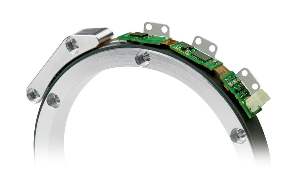
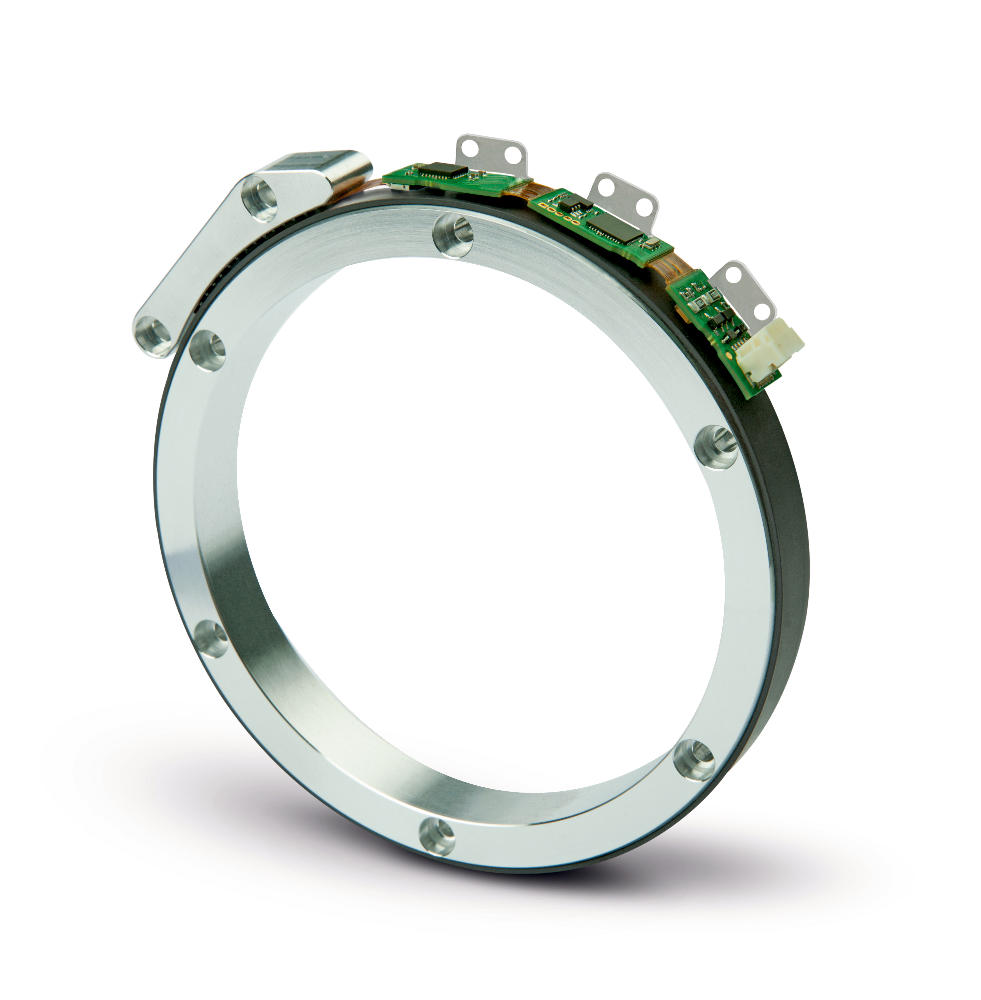
With flexCoder technology, the MSAC200 can be flexibly adapted to the customers design and provides precise absolute values with high installation tolerances at the same time. It is basically possible to adapt the encoder and the magnetic ring for precise fitting, for example in motors. An additional feature is the high reading distance ≤0.6 mm and axial tolerance of ±0.5 mm to facilitate the design of the overall system and enable use in dynamic applications.
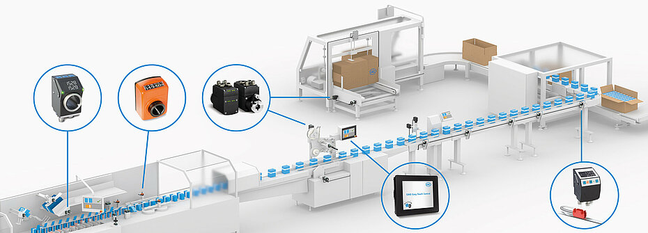
- Industrial and medical applications e.g., motor feedback, handling automation and robotics
- Integration into small installation space possible
- Absolute resolution up to 20 Bit
- Repeatability 0.01°
- Reading distance ≤0.6 mm
- Interface BiSS C, SSI
- Optionally analog Sin/Cos 1 Vss or digital line driver
- Magnetic absolute encoder single-turn
- Industry 4.0 ready
Technical drawing
Technical Specifications
Mechanical data
Electrical data
System data
Ambient conditions
Feature
Technical Specifications
Enhancement
Weight
15
 g
Housing design
 open circuit board
Material
 aluminum
reader head
Sensor/ring reading distance
≤0.6
 mm
Feature
Technical Specifications
Enhancement
Operating voltage
4.5 … 30 V DC
reverse polarity protection
Power input
<1.5
 W
Output circuit
 LD, 1 Vpp
Interface
 BiSS C, SSI
Real-time requirement
 speed-proportional signal output
sin/cos output
Type of connection
 JST plug connector
SM10B-GHDS-A-GAN-TF
Ausgangsschaltung LD
Feature
Technical Specifications
Enhancement
Output signals
A, /A, B, /B
Output signal level high
>2.5
 V
Output signal level low
<0.5
 V
Ausgang Sin/Cos
Feature
Technical Specifications
Enhancement
Output signals
 sin, /sin, cos, /cos
Output voltage
1 VPP ±10%
 at 0 … 70 °C
120 Ω teminal resistance
Signal period
2000
 µm
Signal pattern, Sin/Cos output
E: reference voltage 2.5 V
F: 1 VSS±10%
M: 90°±1.0° /±3° (25 kHz)
F: 1 VSS±10%
M: 90°±1.0° /±3° (25 kHz)
Signal pattern, LD output circuit
Pulse interval, LD output circuit
Feature
Technical Specifications
Enhancement
Pole length
2
 mm
incremental track
Resolution
 system resolution absolute = scaling factor absolute (MSAC200) * number of poles (MRAC200)
with SSI, BiSS C interface
 system resolution incremental = scaling incremental (MSAC200) * number of poles (MRAC200) * 4
with LD output circuit
2
 mm
with 1 Vpp output circuit
Scaling factor
8
 bit
 absolute
,
9
,
10
,
11
8
,
9
,
10
,
11
 bit
System accuracy
±0.155
 °
with 70 poles with mechanical concentricity of the system ≤ 100 µm
±0.131
 °
with 86 poles with mechanical concentricity of the system ≤ 100 µm
±0.114
 °
with 102 poles with mechanical concentricity of the system ≤ 100 µm
±0.096
 °
with 128 poles with mechanical concentricity of the system ≤ 100 µm
±0.082
 °
with 158 poles with mechanical concentricity of the system ≤ 100 µm
±0.085
 °
with 224 poles with mechanical concentricity of the system ≤ 150 µm
±0.071
 °
with 396 poles with mechanical concentricity of the system ≤ 200 µm
Repeat accuracy
0.01
 °
unidirectional
Measuring range
≤360
 °
singelturn
Circumferential speed
≤5
 m/s
absolute
≤25
 m/s
incremental (sin/cos)
Incremental LD peripheral speed
Peripheral speed Vmax [m/s] |
|||||||
Incremental scaling [bit] |
8 |
15.63 |
7.81 |
3.13 |
1.56 |
0.78 |
0.31 |
9 |
7.81 |
3.91 |
1.56 |
0.78 |
0.39 |
0.16 |
|
10 |
3.91 |
1.95 |
0.78 |
0.39 |
0.20 |
0.08 |
|
11 |
1.95 |
0.95 |
0.39 |
0.20 |
0.10 |
0.04 |
|
Pulse interval [μs] |
0.10 |
0.20 |
0.50 |
1.00 |
2.00 |
5.00 |
|
Counting frequency [kHz] |
2500.00 |
1250.00 |
500.00 |
250.00 |
125.00 |
50.00 |
|
3 |
1 |
2 |
2 |
2 |
2 |
2 |
2 |
Information on the speed as a function of the number of poles of the magnetic rings can be found in the assembly instructions.
Feature
Technical Specifications
Enhancement
Ambient temperature
-40 … 105 °C
Storage temperature
-40 … 105 °C
without packaging
Relative humidity
95
 %
condensation inadmissible
EMC
 EN 61000-6-2
interference resistance / immission
 EN 61000-6-4
Interference emission/immission (EMC according to the standards listed is ensured when the motor feedback system is mounted in an electrically conductive housing connected to the central grounding point of the motor regulator via a cable shield. If other shield concepts are used, the user must carry out his own tests.)
Protection category
 IP00
Shock resistance
≤1000 m/s2, 6 ms
EN 60068-2-27, 3 axes (+/-), each 3 shocks
Vibration resistance
≤200 m/s2, 10 … 2000 Hz
EN 60068-2-6, 3 axes, each 20 cycles
More information
pin assignment
SSI |
BiSS C |
PIN |
B, Cos+ |
B, Cos+ |
1 |
/B, Cos- |
/B, Cos- |
2 |
A, Sin+ |
A, Sin+ |
3 |
/A, Sin- |
/A, Sin- |
4 |
T- |
NMA |
5 |
D- |
NSLO |
6 |
T+ |
MA |
7 |
D+ |
SLO |
8 |
UB |
UB |
9 |
GND |
GND |
10 |
Industry 4.0
In most cases, data exchange with the magnetic encoders is limited to the exchange of process data. In addition to the process data, intelligent drives provide additional information that can be evaluated for condition monitoring up to predictive maintenance:
Process data |
Smart Value |
Smart Function |
Actual position |
Temperature |
Plausibility monitoring |
Hint for mounting
When you mount the sensor and magnetic tape, please be careful to align both system components correctly.
A, Sensor/tape reading distance |
0.1 … 0.6 mm |
B, Lateral offset |
±0.5 mm |
C, Alignment error |
±0.5° |
Symbolic representation
System components
Purchase order
Product configuration
Feature
Select specifications
Enhancement
Select your specifications:
design
70
Interface
BiSS/C
absolute scaling
8
incremental scaling
8
Pulse interval
0.1
in µs
Scope of delivery
- MSAC200
- Quick Start Guide