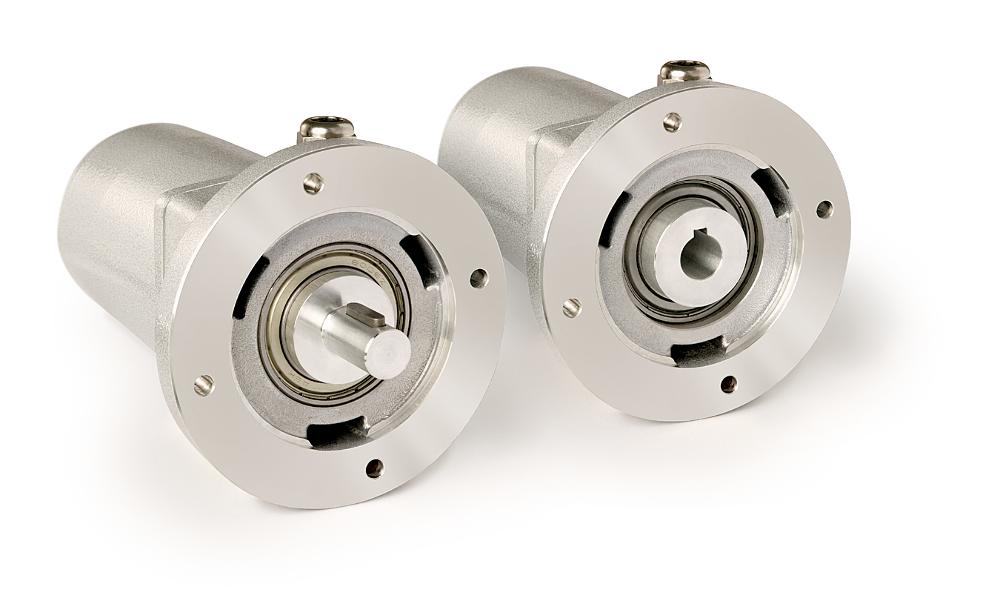
Geared potentiometer GP44
With solid or blind hole shaft
- Extremely resistant to external influences
- Solid or blind-hole hollow shaft, max. Ø 20 mm
- Adaptation to various measurement distances owing to a wide range of gear ratios
- Integrated slip clutch to protect the potentiometer
- Potentiometer or power output
- IP65 protection class
- Up to 3 cam-operated switch outputs, freely adjustable
Technical drawing
Technical Specifications
Mechanical data
Electrical data
System data
Ambient conditions
Feature
Technical Specifications
Enhancement
shaft
 aluminum
Housing
 aluminum
Gear ratio
0.2 … 512
Speed
≤500
 min-1
depending on transmission
Shaft load rating
≤1000
 N
radial, solid shaft
≤1700
 N
axial
Potentiometer service life
1 x 10⁶ rotation(s)
Geber Potentiometer Typ 02, 10 Wendel
Feature
Technical Specifications
Enhancement
Power rating
2
 W
 at 70 °C
≤30 V
resistance
1
 kΩ
,
5
,
10
 kΩ
Resistance tolerance
±5
 %
Standard terminal resistance
0.2
 %
Linearity tolerance
±0.25
 %
Design
 wire
Geber Potentiometer Typ 03, 10 Wendel
Feature
Technical Specifications
Enhancement
Power rating
2
 W
 at 70 °C
≤30 V
resistance
1
 kΩ
,
5
,
10
 kΩ
Resistance tolerance
±5
 %
Standard terminal resistance
0.2
 %
Linearity tolerance
±0.25
 %
Design
 hybride
Geber Potentiometer Typ 03/0.1, 10 Wendel
Feature
Technical Specifications
Enhancement
Power rating
2
 W
 at 70 °C
≤30 V
resistance
5
 kΩ
,
10
 kΩ
Resistance tolerance
±5
 %
Standard terminal resistance
0.2
 %
Linearity tolerance
±0.1
 %
Design
 hybride
Messwandler, Stromausgang
Feature
Technical Specifications
Enhancement
Operating voltage
24 V DC ±20 %
Output current
4 … 20 mA
 at load 500 Ω
Load capacity of the switching cams
Feature
Technical Specifications
Enhancement
Measuring range
340° ±5°
 (mechanical full-length)
potentiometer type 01
3600° +10°
potentiometer types 02, 03, 03/0.1
Feature
Technical Specifications
Enhancement
Ambient temperature
-20 … 80 °C
Relative humidity
condensation inadmissible
EMC
 EN 61000-6-2
interference resistance / immission
 EN 61000-6-4
emitted interference / emission
Protection category
 IP52
EN 60529
More information
pin assignment
Potentiometric outputs P01, P05, P10
Signal |
Terminal |
Po |
11 |
Pe |
13 |
S |
12 |
MMW transducer
Signal |
Terminal |
I+ |
12 |
I- |
11 |
nc |
13 |
Cam
Assignment |
Switch cam A Terminal |
Switching cam B terminal |
Switching cam C terminal |
3 |
4 |
7 |
|
2 |
5 |
8 |
|
1 |
6 |
9 |
Purchase order
Gear ratio calculation
Switch cam order
Digit 1 |
"Digit 2 " |
Digit 3 |
Ordering data |
Cam shape 2 |
2 |
||
Cam shape 1 |
Cam shape 3 |
13 |
|
Cam shape 1 |
Cam shape 2 |
Cam shape 3 |
123 |
Example of order table, characteristic G
Product configuration
Feature
Select specifications
Enhancement
Select your specifications:
Gear ratio
0.1/10
drive shaft
H/20
potentiometer type
01
resistance
1
transducer
MMW
only only for resistance 10 and potentiometer type 02 or 03
Sense of rotation
<leer>
only for OMW transducer
only for MMW transducer
cam/
form
1
switching voltage
1
Scope of delivery
- GP44
- Installation Instructions