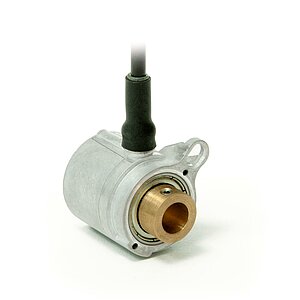
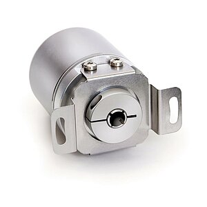
Geared potentiometer GP02
Compact design with through hollow shaft
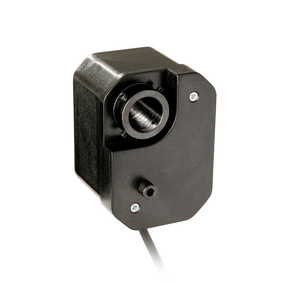
- Through hollow shaft Ø 14 mm
- Adaptation to various measurement distances owing to a wide range of gear ratios
- Compact, low-cost design
- Potentiometer or power output
- Easy mounting


Technical drawing

Technical data
Encoder potentiometer type 01,1 helix
Encoder potentiometer type 02,10 helices
Encoder potentiometer type 03, 10 helices
Encoder potentiometer type 03/0.1, 10 helices
Transducer, power output
More information
pin assignment
Potentiometric outputs P01, P05, P10
|
Signal |
|
|
Po |
brown |
|
Pe |
white |
|
S |
green |
MMW transducer
|
Signal |
Cable color |
|
I+ |
brown |
|
I- |
white |
Order
Gear ratio calculation
Product configuration
Feature
Select specifications
Additional information
Gear ratio
0.2
torque pin/
form
A
potentiometer type
01
resistance
1
Sense of rotation
<leer>
Cable length
00.5
Comparable products
Scope of delivery
- GP02
- Installation Instructions


