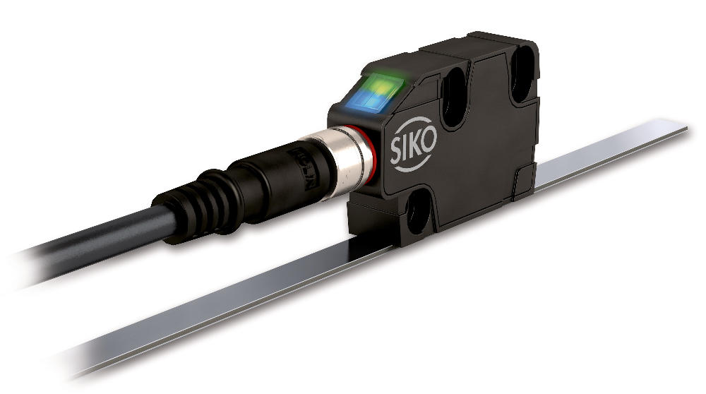
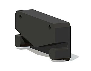
Magnetic sensor MSC500
Compact sensor, incremental, digital interface, resolution 1 μm
- max. resolution 1 μm
- max. 200000 pulses/revolution in conjunction with MR500 or MBR500 (160 poles)
- Repeat accuracy ±0.005 mm
- Status LED with integrated distance monitoring
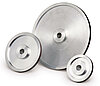
- Works with magnetic tape MB500/1, magnetic ring MR500, magnetic band ring MBR500
- Reading distance ≤2 mm
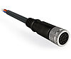
- Sensor connection can be plugged with KV1C cable extension
- Output circuit PP, TTL, LD (depending on the operating voltage)
- optionally with reference point R or flexible reference marks FR


Technical drawing

Technical data
Travel/circumferential speed
|
Travel/circumferential speed Vmax [m/s] |
|||||||||||
|
Resolution/ Scaling factor |
0.001/1250 |
4.00 |
3.20 |
1.60 |
0.80 |
0.32 |
0.20 |
0.10 |
0.05 |
0.03 |
0.01 |
|
0.005/250 |
20.00 |
16.00 |
8.00 |
4.00 |
1.60 |
1.00 |
0.50 |
0.25 |
0.13 |
0.06 |
|
|
0.01/125 |
25.00 |
25.00 |
16.00 |
8.00 |
3.20 |
2.00 |
1.00 |
0.50 |
0.25 |
0.12 |
|
|
0.025/50 |
25.00 |
25.00 |
25.00 |
20.00 |
8.00 |
5.00 |
2.50 |
1.25 |
0.63 |
0.30 |
|
|
0.05/25 |
25.00 |
25.00 |
25.00 |
25.00 |
16.00 |
10.00 |
5.00 |
2.50 |
1.25 |
0.61 |
|
|
0.1/12.5 |
25.00 |
25.00 |
25.00 |
25.00 |
25.00 |
20.00 |
10.00 |
5.00 |
2.50 |
1.21 |
|
|
Pulse interval [μs] |
0.20 |
0.25 |
0.50 |
1.00 |
2.50 |
4.00 |
8.00 |
16.00 |
32.00 |
66.00 |
|
|
Counting frequency [kHz] |
1250.00 |
1000.00 |
500.00 |
250.00 |
100.00 |
62.50 |
31.25 |
15.63 |
7.81 |
3.79 |
|
|
3 |
2 |
1 |
1 |
1 |
1 |
1 |
1 |
1 |
1 |
1 |
1 |
Signal image
Note
The logical condition of signals A and B is not defined in reference to the index signal I or the reference signal R. It can deviate from the signal form.
Pulse interval, LD output circuit
More information
pin assignment
in conjunction with cable extension KV1C
|
Signal |
4-core |
5-core |
6-core |
8-core |
|
A |
red |
red |
red |
red |
|
B |
orange |
orange |
orange |
orange |
|
I, R, FR |
blue |
blue |
||
|
+UB |
brown |
brown |
brown |
brown |
|
GND |
black |
black |
black |
black |
|
/A |
yellow |
yellow |
||
|
/B |
green |
green |
||
|
/I, /R, /FR |
violet |
Hint for mounting
|
Reference signal |
I |
R |
FR |
|
A, Sensor/tape reading distance |
≤2 mm |
≤1.5 mm |
0.4 … 1 mm |
|
B, Lateral offset |
±2 mm |
±0.5 mm |
±0.5 mm |
|
C, Alignment error |
±3° |
±3° |
±3° |
|
D, Longitudinal inclination |
±1° |
±1° |
±1° |
|
E, Lateral inclination |
±3° |
±3° |
±3° |
|
3 |
2 |
2 |
2 |


Order
Product configuration
Feature
Select specifications
Additional information
reference signal
I
linear resolution/
radial scaling factor
0.001/1250
Pulse interval
0.2
Scope of delivery
- MSC500
- Fastening set
- Quick Start Guide