Headquarters: SIKO GmbH Weihermattenweg 2 79256 Buchenbach Germany Phone+49 7661 394-0

Magnetic sensor MSA213K

High-resolution absolute, numerous interfaces, swivel-mounted plug

open expert video
The absolute encoder MSA213K convinces with its high absolute resolution of 1 µm for precise position detection and a high reading distance of up to 0.8 mm at the same time. With the absolutely coded magnetic tape MBA213, measurements over a length of up to 16 meters are possible. Different absolute interfaces are available for integration into the control environment, which can be supplemented by incremental (LD) or analog (1 Vss) signal outputs for rapid regulation. The swivel-mounted M12 plug enables easy integration into the application on the customer side. The MSA213K is compatible with the MSA111C and can be used as an alternative with a higher reading distance and a longer absolute travel distance.

Profile MSA213K:

  • High absolute resolution 1 μm
  • Repeat accuracy max. ±1 μm
  • Reading distance ≤0.8 mm
  • Measuring range 0 … 16 m
  • Function and status display LED
  • Interface BiSS C, SSI, IO-Link
  • Optionally analog Sin/Cos 1 Vss or digital line driver
  • Connection technology M12 (A-coded), swivel-mounted
  • Industry 4.0 ready
IO-Link BiSS C SSI

Inquire about product/Add to leaflet
Mechanical data
FeatureTechnical dataAdditional information
Housingzinc die-cast
Sensor/band reading distance≤0.8 mm
Weight~0.095 kg
Electrical data
FeatureTechnical dataAdditional information
Operating voltage7.5 … 30 V DC reverse polarity protected (IOL)
Current consumption<200 mA
Status displayRGB-LED plausibility error, distance warning, device status
Output circuitwithout, LD
InterfaceSSI, BiSS C, IO Link
Type of connectionM12 connector (A-coded) 12-pole, 1x pin (IOL)
M12 connector (A-coded) 4-pole, 1x pin (IOL)
Signal pattern, Sin/Cos output
E: reference voltage 2.5 V
F: 1 VSS ±10%
M: 90° ±1.0° / ±3° (25 kHz)
Signal pattern, LD output circuit
Pulse interval, LD output circuit
System data
FeatureTechnical dataAdditional information
Pole length2 mm incremental
Resolution1 µm absolute
1, 5, 10 µm LD, incremental
Linearity deviation±10 µm
Repeat accuracy ±1 µm
Measuring range≤16384 mm
Travel speed≤5 m/s absolute
Travel speed, LD output circuit
  Travel speed Vmax [m/s]
Resolution [µm] 1 10.00 5.00 2.00 1.00 0.50 0.20
5 25.00 25.00 10.00 5.00 2.50 1.00
10 25.00 25.00 20.00 10.00 5.00 2.00
Pulse interval [μs] 0.10 0.20 0.50 1.00 2.00 5.00
Counting frequency [kHz] 2500.00 1250.00 500.00 250.00 125.00 50.00
Ambient conditions
FeatureTechnical dataAdditional information
Ambient temperature-40 … 85 °C
Storage temperature-40 … 85 °C
Relative humidity100 % condensation admissible
EMCEN 61000-6-2 interference resistance / immission, class B emission limit
EN 61000-6-4 interference emission / emission, class B emission limit
Protection categoryIP67 EN 60529, with mating connector fitted
Shock resistance≤500 m/s2, 11 ms EN 60068-2-27, half-sine, 3 axes (+/-), each 3 pulses
Vibration resistance≤100 m/s2, 10 … 2000 Hz

EN 60068-2-6, 3 axes, each 10 cycles

Magnetic sensor MSA213K
Pin assignment
SSI interface, BiSS C without LD, 1 Vss
SSIBiSS CPIN
nc nc 1
D+ SLO 2
D- NSLO 3
T- NMA 4
+UB +UB 5
nc nc 6
nc nc 7
nc nc 8
nc nc 9
nc nc 10
T+ MA 11
GND GND 12
IO-Link interface with LD, 1 Vss
SignalPIN
nc 1
nc 2
nc 3
nc 4
L+ (+UB) 5
/A, Sin- 6
A, Sin+ 7
/B, Cos- 8
B, Cos+ 9
C/Q 10
I/Q 11
L- (GND) 12
SSI interface, BiSS C with LD, 1 Vss
SSIBiSS CPIN
nc nc 1
D+ SLO 2
D- NSLO 3
T- NMA 4
+UB +UB 5
/A, Sin- /A, Sin- 6
A, Sin+ A, Sin+ 7
/B, Cos- /B, Cos- 8
B, Cos+ B, Cos+ 9
nc nc 10
T+ MA 11
GND GND 12
IO-Link interface without LD, 1 Vss
SignalPIN
L+ (+UB) 1
I/Q 2
L- (GND) 3
C/Q 4
Industry 4.0
In most cases, data exchange with the magnetic encoders is limited to the exchange of process data. In addition to the process data, intelligent drives provide additional information that can be evaluated for condition monitoring up to predictive maintenance:
Process DataSmart ValueSmart Function
Actual position -- Plausibility monitoring
Hint for mounting
When you mount the sensor and magnetic tape, please be careful to align both system components correctly. The arrow marks on the tape and sensor must point in the same direction when mounting the components.
A, Sensor/tape reading distance ≤0.8 mm
B, Lateral offset ±0.6 mm
C, Alignment error ±1°
D, Longitudinal tilt max. sensor/tape A reading distance must never be exceeded.
E, Lateral tilt max. sensor/tape A reading distance must never be exceeded.

MSA213K Hint for mounting
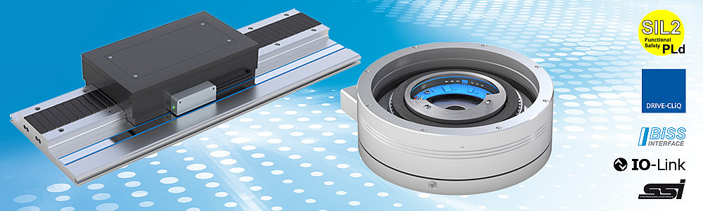
Symbolic representation

Scope of delivery
  • MSA213K
  • distance gage
  • Quick Start Guide
Ordering table
Feature Order data Specifications Additional information
Incremental resolution
A...
1, 5, 10 in µm
no information required
 
Pulse interval
B...
0.1, 0.2, 0.5, 1, 2, 5 in µs
no information required
 
Ordering key
MSA213K
-
E12X
-
IOL
-
LD
-
A
-
B
-
S