


E: reference voltage 2.5 V
F: 1 VSS ±10%
M: 90° ±1.0° / ±3° (25 kHz)
Headquarters: SIKO GmbH Weihermattenweg 2 79256 Buchenbach Germany Phone+49 7661 394-0 info@siko-global.com
Headquarters: SIKO GmbH Weihermattenweg 2 79256 Buchenbach Germany Phone+49 7661 394-0 info@siko-global.com
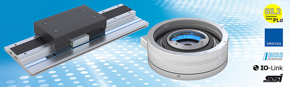


| Feature | Technical data | Additional information |
|---|---|---|
| Housing design | open printed circuit board | |
| Material | aluminum | reader head |
| Sensor/ring reading distance | ≤0.6 mm | |
| Weight | 15 g |
| Feature | Technical data | Additional information |
|---|---|---|
| Operating voltage | 4.5 … 30 V DC | reverse polarity protection |
| Power input | <1.5 W | |
| Output circuit | LD, 1 Vpp | |
| Interface | BiSS C, SSI | |
| Real-time requirement | signal output proportional to speed | Sin Cos output |
| Type of connection | JST connector | SM10B-GHDS-A-GAN-TF |
| Feature | Technical data | Additional information |
|---|---|---|
| Output signals | sin, /sin, cos, /cos | |
| Output voltage | 1 VPP ±10% | at 0 ... 70° C, 120 Ω terminating resistor |
| Signal period | 2000 µm |
| Feature | Technical data | Additional information |
|---|---|---|
| Output signals | A, /A, B, /B | |
| Output signal level high | >2.5 V | |
| Output signal level low | <0.5 V |


| Feature | Technical data | Additional information |
|---|---|---|
| Pole length | 2 mm | incremental track |
| Resolution | system resolution absolute = scaling factor absolute (MSAC200) * number of poles (MRAC200) | with SSI, BiSS C interface |
| system resolution incremental = scaling incremental (MSAC200) * number of poles (MRAC200) * 4 | with LD output circuit | |
| 2 mm | with 1 Vpp output circuit | |
| Scaling factor | 8, 9, 10, 11 bit absolute | |
| 8, 9, 10, 11 bit incremental | ||
| System accuracy | ±0.155° | with 70 poles with mechanical concentricity of the system ≤ 100 µm |
| ±0.131° | with 86 poles with mechanical concentricity of the system ≤ 100 µm | |
| ±0.114° | with 102 poles with mechanical concentricity of the system ≤ 100 µm | |
| ±0.096° | with 128 poles with mechanical concentricity of the system ≤ 100 µm | |
| ±0.082° | with 158 poles with mechanical concentricity of the system ≤ 100 µm | |
| ±0.085° | with 224 poles with mechanical concentricity of the system ≤ 150 µm | |
| ±0.071° | with 396 poles with mechanical concentricity of the system ≤ 200 µm | |
| Repeat accuracy | 0.01° | unidirectional |
| Measuring range | ≤360° | Singleturn |
| Circumferential speed | ≤5 m/s | absolute |
| ≤25 m/s | incremental (Sin/Cos) |
| Feature | Technical data | Additional information |
|---|---|---|
| Ambient temperature | -40 … +105 °C | |
| Storage temperature | -40 … +105 °C | without packaging |
| Relative humidity | 95 % | condensation not permitted |
| EMC | EN 61000-6-2 | interference resistance/immission |
| EN 61000-6-4 | interference resistance / immission (EMC according to the standards listed is ensured when the motor feedback system is mounted in an electrically conductive housing connected to the central grounding point of the motor regulator via a cable shield. If other shield concepts are used, the user must carry out his own tests.) | |
| Protection category | IP00 | |
| Shock resistance | ≤1000 m/s2 , 6 ms | EN 60068-2-27, 3 axes (+/-), each 3 shocks |
| Vibration resistance | ≤200 m/s2 , 10 ... 2000 Hz | EN 60068-2-6, 3 axes, each 20 cycles |


Symbolic representation

