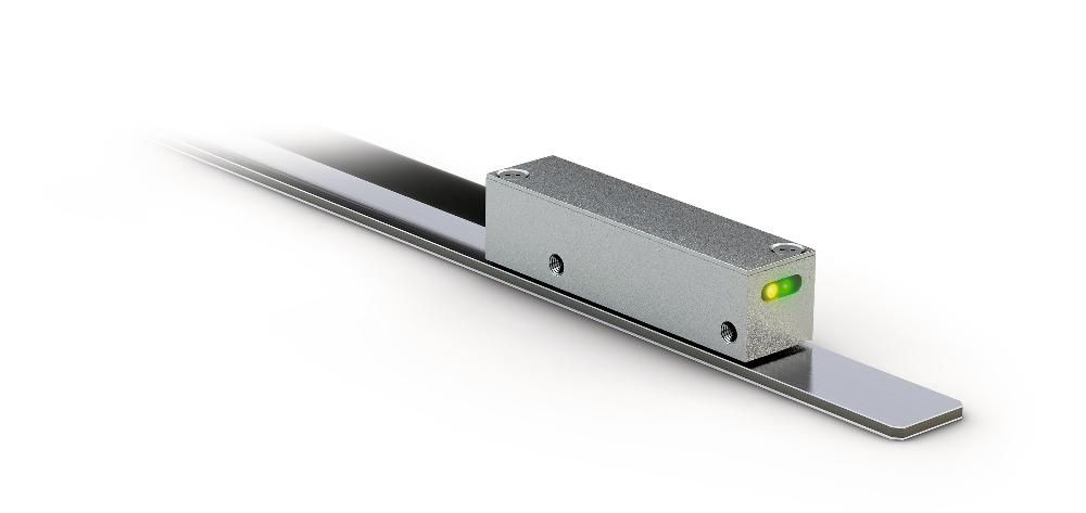
Magnetic sensor LEC100
Incremental, digital or analog interface, very small design
- Repeat accuracy max. ±1 μm
- Max. resolution 0.1 µm (LD output circuit)
- Reading distance 0.1 … 0.4 mm
- Works with MB100/1 magnetic tape
- Signal period 1000 μm
- Output circuit sin/cos or LD
- Function and status display LEDs


Technical drawing

Technical data
LD output circuit
Sin/cos output
Signal pattern, Sin/Cos output
F: 1 VSS ±10 %
L: 180° ±40 %
M: 90° ±1.0° / ±3° (25 kHz)
X: 1 VSS
Signal pattern, LD output circuit
Note
The logic status of signals A and B is not defined regarding the reference signal RD or R. It may deviate from the signal pattern.
Note
Reference or index signal with 4 increments (360°) signal length is only valid from the 5th counting step onwards. A corresponding delay should be taken into consideration after switching on the operating voltage.
Pulse interval, LD output circuit
Travel speed
|
Travel speed Vmax [m/s] |
|||||||
|
Resolution [µm] |
0.1 |
0.80 |
0.40 |
0.32 |
0.16 |
0.08 |
0.04 |
|
0.2 |
1.60 |
0.80 |
0.64 |
0.32 |
0.16 |
0.08 |
|
|
0.5 |
4.00 |
2.00 |
1.60 |
0.80 |
0.40 |
0.20 |
|
|
1 |
8.00 |
4.00 |
3.20 |
1.60 |
0.80 |
0.40 |
|
|
2 |
16.00 |
8.00 |
6.40 |
3.20 |
1.60 |
0.80 |
|
|
5 |
25.00 |
20.00 |
16.00 |
8.00 |
4.00 |
2.00 |
|
|
10 |
25.00 |
25.00 |
25.00 |
16.00 |
8.00 |
4.00 |
|
|
Pulse interval [μs] |
0.10 |
0.20 |
0.25 |
0.50 |
1.00 |
2.00 |
|
|
Counting frequency [kHz] |
2500.00 |
1250.00 |
1000.00 |
500.00 |
250.00 |
125.00 |
|
|
3 |
1 |
2 |
2 |
2 |
2 |
2 |
2 |
More information
pin assignment
|
Signal Sin/Cos |
"Signal LD " |
Cable color |
|
sin |
A |
red |
|
cos |
/A |
yellow |
|
I, RD |
"I, R " |
blue |
|
+UB |
+UB |
brown |
|
GND |
GND |
black |
|
/sin |
B |
orange |
|
/cos |
/B |
green |
|
/I, /RD |
/I, /R |
violet |
Hint for mounting
|
Reference signal |
R, RD |
I |
|
A, Sensor/tape reading distance |
0.1 … 0.2 mm |
0.1 ... 0.4 mm |
|
B, Lateral offset |
±0.5 mm |
±0.5 mm |
|
C, Alignment error |
±3° |
±3° |
|
D, Longitudinal inclination |
±1° |
±1° |
|
E, Lateral inclination |
±3° |
±3° |
|
3 |
2 |
2 |
System components

Order
Product configuration
Feature
Select specifications
Additional information
Cable length
01.0
Output circuit
1Vss
reference signal
I
Resolution
<leer>
Pulse interval
<leer>
Scope of delivery
- LEC100
- Quick Start Guide

