


| Travel/circumferential speed Vmax [m/s] | |||||||||||
|---|---|---|---|---|---|---|---|---|---|---|---|
| Resolution/ Scaling factor | 0.001/1250 | 4.00 | 3.20 | 1.60 | 0.80 | 0.32 | 0.20 | 0.10 | 0.05 | 0.03 | 0.01 |
| 0.005/250 | 20.00 | 16.00 | 8.00 | 4.00 | 1.60 | 1.00 | 0.50 | 0.25 | 0.13 | 0.06 | |
| 0.01/125 | 25.00 | 25.00 | 16.00 | 8.00 | 3.20 | 2.00 | 1.00 | 0.50 | 0.25 | 0.12 | |
| 0.025/50 | 25.00 | 25.00 | 25.00 | 20.00 | 8.00 | 5.00 | 2.50 | 1.25 | 0.63 | 0.30 | |
| 0.05/25 | 25.00 | 25.00 | 25.00 | 25.00 | 16.00 | 10.00 | 5.00 | 2.50 | 1.25 | 0.61 | |
| 0.1/12.5 | 25.00 | 25.00 | 25.00 | 25.00 | 25.00 | 20.00 | 10.00 | 5.00 | 2.50 | 1.21 | |
| Pulse interval [μs] | 0.20 | 0.25 | 0.50 | 1.00 | 2.50 | 4.00 | 8.00 | 16.00 | 32.00 | 66.00 | |
| Counting frequency [kHz] | 1250.00 | 1000.00 | 500.00 | 250.00 | 100.00 | 62.50 | 31.25 | 15.63 | 7.81 | 3.79 | |
Headquarters: SIKO GmbH Weihermattenweg 2 79256 Buchenbach Germany Phone+49 7661 394-0 info@siko-global.com


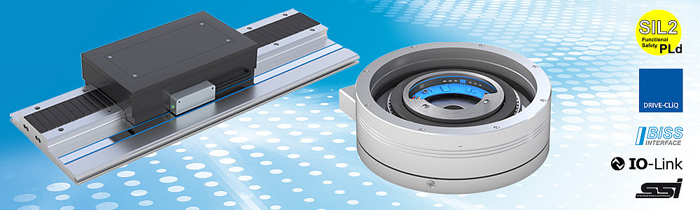
 MR500
MR500 MBR500

